
Precise and reliable signal transmission is crucial in industrial automation. The long-standing industry standard for analog signal transmission is the 4-20 mA current loop. Its continued use stems from its strong resistance to electrical noise and the built-in diagnostic capability of its “live zero” (4 mA), which immediately signals a broken wire or power loss. However, device wiring varies significantly. The correct choice between a 2-wire, 3-wire, or 4-wire configuration must be determined based on the device’s specific power demands, the necessity for signal isolation, and the available budget for installation.
Below is a comprehensive guide to the working functionality, applications, and limitations of 2-wire, 3-wire, and 4-wire transmitters.
2-Wire Transmitters
The 2-wire configuration is the most common and simplest to implement in the field.
Working & Functionality: A 2-wire transmitter uses just two wires to handle both the power supply and the signal transmission. The device draws its operating power directly from the 4-20 mA current loop. The power supply (often provided by a PLC or a dedicated DCS input card) provides the voltage, and the transmitter acts as a variable resistor, modulating the current flowing through the loop between 4 mA (low end of the measurement) and 20 mA (high end). Because it operates on a “live zero,” the transmitter must be highly efficient, operating on less than 4 mA of current.
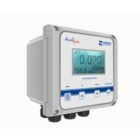
Image: 2-wire transmitter
Applications:
- Basic pressure, temperature, and level transmitters.
- Simple flow sensors and standard field instruments.
- Clean and low-interference environments, such as food and beverage tanks or compact water storage.
Limitations & Disadvantages:
Power Limitations: Because it must operate entirely on the low loop current, it cannot power complex internal electronics, large local displays, or advanced diagnostic features.
Voltage Drops: Long cable runs can cause significant voltage drops, requiring a highly robust power supply to compensate.
Limited Output: Output is generally restricted to basic 4-20 mA analog signals without native support for digital communication or relay alarms.
3-Wire Transmitters
The 3-wire system bridges the gap between the simplicity of a 2-wire setup and the power capacity of a 4-wire setup, though it is less commonly used in modern industrial applications.
Working & Functionality: A 3-wire transmitter uses two wires for an independent power supply and a third, separate wire for the signal output. Because the signal circuit and the power circuit share a common ground (one lead is common to both), only three wires are needed in total. The dedicated power source means the transmitter’s internal electronics do not have to rely on “stealing” power from the 4-20 mA signal loop.
Applications:
- Humidity transmitters and smart devices with large local displays or keypads.
- Transmitters that require significant internal processing power or HART communication protocols.
Limitations & Disadvantages:
Ground Loop Risks: Because the signal and power supply share a common ground wire, there is only partial signal isolation. If not wired correctly, this can lead to ground loops and signal interference.
Safety Restrictions: 3-wire transmitters are not typically designed for intrinsically safe installations in hazardous locations.
Wiring Costs: Requires more wiring and installation effort compared to a 2-wire system.
4-Wire Transmitters
The 4-wire configuration provides the highest degree of signal isolation and is built for heavy-duty applications that demand substantial power.
Working & Functionality: A 4-wire transmitter uses two wires dedicated entirely to the power supply (which can be AC or DC) and two completely separate wires for the signal output. This creates complete galvanic isolation between the power source and the signal loop, which virtually eliminates noise interference and ground loop issues.
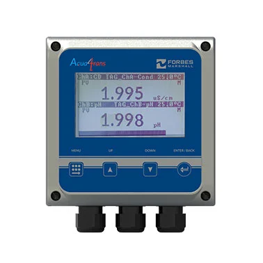
Image: 4-wire transmitter
Applications:
- High-power analytical instruments, such as pH, conductivity, and gas analyzers.
- dvanced flow meters (e.g., Coriolis mass flow, ultrasonic, and electromagnetic flow transmitters).
- Harsh environments requiring explosion-proof certifications (e.g., petrochemical plants, oil refineries) or where mediums are unstable, like vapor-rich wastewater basins.
- Devices needing internal heaters, refrigeration, RS485 communication, or relay outputs for high/low-level alarms.
Limitations & Disadvantages:
High Cost and Complexity: This is the most expensive and complex wiring setup. It requires separate cable routing for power and signal, increasing material and labor costs.
Space Requirements: More wires mean that larger electrical conduits and more space in terminal panels are necessary.
Increased Heat Loss: The built-in mains transformers and higher power capabilities result in increased dimensions and potential heat losses compared to 2-wire transmitters.
Selecting the appropriate transmitter wiring hinges on your system’s requirements, but for the most demanding applications, the 4-wire option stands out. While 2-wire transmitters are the most cost-effective, simplest to set up, and safest for basic measurements, their limited power restricts them to simple operations.
3-wire transmitters offer a moderate power level, allowing for features like digital displays and advanced diagnostics, but they carry the risk of ground loops and do not offer the highest performance.
4-wire transmitters offer the superior solution, featuring the highest performance, unmatched noise immunity, and complete signal isolation. They provide the necessary power capacity to reliably run high-draw devices and sophisticated digital protocols, making them the best choice where performance and reliability are paramount, despite the trade-offs of the highest cost and greater installation complexity.