Flue gases released from the boiler chimney contain gases and particulate matter that
pollute the environment.
Continuous monitoring of stack emission is essential to ensure efficient boiler operations and
adherence to environmental norms.
Why Flue Gas Flow
Measurement?
Just measuring the pollutant concentration does not clearly indicate the impact of emissions on the
environment. It is important to measure the composition and concentration of polluting gases
as well as their ‘flow’, so as to arrive at a total discharge of polluting gases to the atmosphere.
Many key design and operating parameters such as specific collection area, gas velocity
(ft/sec)
and treatment time within the ESP can be determined with the help of gas flow
measurement;
For example significant variations in oxygen would show up as large fluctuations in the
gas flow rate.
This would mean decreased ESP performance, which would in turn necessitate
the need to routinely
determine ESP gas volume.
Some of the indicators of excess flue gas causing decreased ESP performance include :
a) Low SCA (specific collection area) values
b) High velocities
c) Short gas treatment times
d) Higher oxygen levels at nearly full load conditions.
Performance Monitoring
For any boiler operation, performance monitoring is essential in order to establish a
good operation and maintenance program. A record of key operational parameters,
right
from day one of boiler operations serves as baseline data which can be used as a
reference point establishing operating and maintenance trends.
Typical parameters to be monitored include:
- Voltage/current
- Opacity
- Gas temperature
- Gas flow rate and distribution
- Gas composition and moisture
Computation of Total Pollutant Release
Legislation often demands that emission measurements are presented in mg/Nm³ where
the expressed volume has been normalised to a standard temperature, pressure and
Oxygen/CO concentration, and where the effects of dilution by water vapour have been
removed.
To compute a measurement of the total pollutant release to atmosphere in kg/hr (or
tonnes/annum), it is necessary to know:
- The pollutant concentration in
mg/m³
- The hot gas flow in m/s
- The cross sectional area at the
point of measurement in m²
The total release is then
calculated as follows:
Mass flow = Mass concentration x
Gas velocity x Area of Duct.
It is vital that all measurements are
made on the same basis. Attempting
to make this calculation using an
actual hot wet gas flow in m/s and
a normalized gas concentration in
mg/Nm³ will produce significant
errors.
Conventional Methods of Flue Gas Monitoring
The commonly used gas flow
monitoring techniques are :
- Ultrasonic Pulse Detection
- Differential Pressure
- Thermal Detection
In all these techniques, the flow monitors (including controller, pressure and temperature
transmitter) are stack or duct mounted.
Ultrasonic Flow Monitors
In case of ultrasonic flow monitoring, the volumetric flow rate of stack gas is measured
by transmitting ultrasonic pulses across the stack in both directions. The time taken to
traverse the distance of the stack, traveling with and against the flow is a function of the
sound velocity and the effluent velocity. The angle at which the ultrasonic pulses need to
traverse the stack or duct is important and is critical to the success of this type of
measurement.
Differential Pressure Flow Monitors
These flow meters work on the principle of measuring differential pressure. They include
S-type pitot tube type, dual-manifold pitot probe type, and annubar type. All these
differential pressure flow rate systems comprise of an electronic, flow-indicating
transmitter that receives pressure and temperature signals from the stack, calculates the
exhaust gas flow rate, and automatically performs electronic drift checks and system
purging. These flowmeters require a lower investment, but are not very accurate and are
susceptible to signal distortion and failure. One of the main limitations is the possible
need to include valves between primary and secondary devices to facilitate removal of
secondary devices for repair or replacement.
Thermal Flow Monitors
These flow monitors measure the electric power required to maintain a constant
temperature of around 24 to 38 Deg.C. above the exhaust gas temperature in a flow
sensor. Both single-point and multi-point analysis options are available in the market.
However, the use of these types of flow meters is limited to clean, non-abrasive fluids.
Even the slightest moisture can lead to measurement inaccuracy. It is essential to know
thermal properties of the gases, as variation from the calibrated values can result in
inaccurate readings.
In-situ Non-contact Measurement : The Preferred Technology
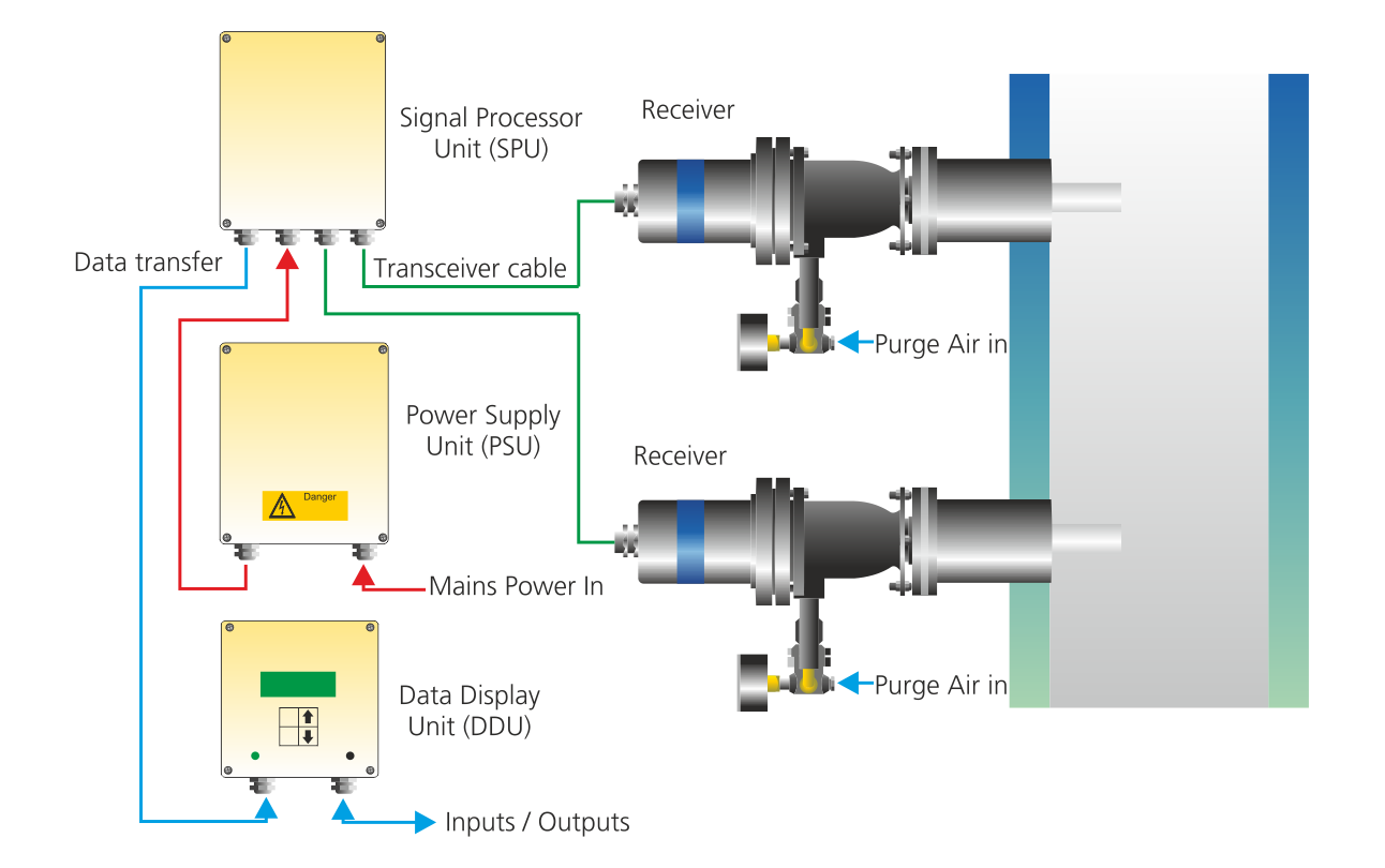
As seen above, conventional methods are not very accurate. The modern in-situ
technology provides accurate and reliable results. These analysers provide non-contact
measurement of gas velocity using a time-delay correlation of flue gas infrared
emissions received by two detectors placed at a fixed distance apart, and are easy to
operate and maintain.
This technique is suitable for all combustion gases, including hot gases and gases with a
high dust burden. Two robust infrared detectors are used for prime sensing. These
detectors are mounted on the stack or duct, typically one meter apart in the direction of
flow. High efficiency air curtains are also fitted, which extend the time between
maintenance periods and window cleaning.
Principle of Operation
The method used is similar in principle to the technique of flow measurement by the
injection of chemical dye or radioactive tracers, where the velocity is derived from the
transport time of the tracer between two measuring points that are known distance
apart.
Instead of an artificial tracer being added, the naturally occurring turbulence of the gas
stream is used as the tracer. This flow turbulence causes fluctuations to occur in infrared
radiation emitted by the gas. This continuously variable turbulent pattern is monitored by
two infrared detectors mounted typically one meter apart along the direction of gas flow.
An electronic correlation technique is used to continuously compare the two detector
signals to determine the time delay between these signals imposed by the gas velocity.
Typical signals from the sensor A and B are shown here.
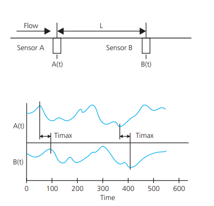
The signal from sensor B shows a strong similarity to that from sensor A. This signal
from sensor B is delayed by a time t, which is the time taken for the gas to flow from
point A to point B. Continuous determination of the detector signal time delay by the
signal processor unit produces a continuous measurement of gas velocity since Velocity
V = L/t, where L is the distance between two sensors.
Benefits
- Accurate and reliable
- Suitable for hot, dusty and aggressive gases
- No moving components, hence easy to maintain
- Low maintenance ensures high measurement availability
- Available with automated span checks for high and low span
- Results available locally due to local digital display and control unit