
Guide to Turbine Vibration Monitoring: Protecting Critical Industrial Assets
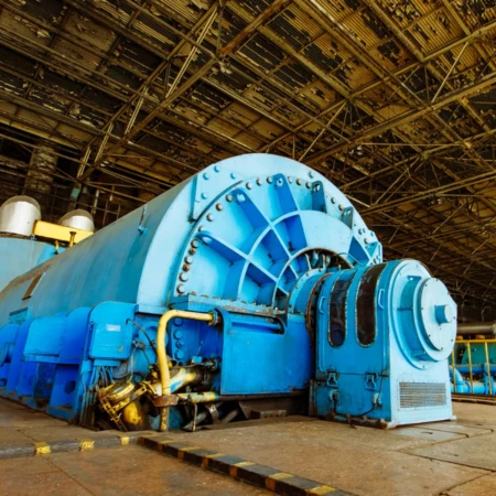
Steam and gas turbines are the heart of power generation. They operate at incredibly high speeds and under immense thermal stress, even the slightest mechanical anomaly can escalate into catastrophic failure.
This is where a Turbine Supervisory Instrument (TSI) system comes into play. Monitoring turbine vibration is not just about detecting failures before they happen but it is also about optimising efficiency, reducing power consumption, and extending the lifespan of expensive assets.
In this article, we dive deep into the fundamentals of turbine vibration monitoring, the essential parameters to track, and how to select the right sensors for your application.
Why Monitor Turbine Vibration?
Running a steam turbine until it breaks down is a recipe for financial disaster. Unmonitored, undesirable steam turbine vibration leads to:
Severe Mechanical Damage: Forcing costly repairs or entire machinery replacement.
- High Power Consumption: Excess energy is conmsumed to simply sustain the unwanted vibrational motion rather than performing functional work.
- Production Downtime and Disrupting Supply: Sudden breakdowns halt production lines, leading to supply chain bottlenecks .
- Occupational Hazard: Severe structural shaking and noise create unsafe environments for plant personnel and even leading to accidents.
By implementing a continuous predictive maintenance programme, plant engineers can schedule repairs during planned turnarounds, ensuring parts are on hand and minimsing downtime and losses.
Key Parameters Measured in a Turbine Supervisory Instrument (TSI) System
A robust Turbine Supervisory Instrument (TSI) system provides a holistic view of turbine health. While bearing vibration often gets the most attention, a complete system monitors several critical parameters simultaneously:
- Radial Vibration
Considered the heart of any TSI system, radial vibration measures the dynamic motion of the shaft perpendicular to its centerline. Modern installations typically use two proximity probes mounted 90° apart (X and Y configuration) from the top vertical center. This configuration allows engineers to view a true circular orbit of the rotating shaft on an oscilloscope. - Thrust Position (Axial Movement)
Thrust monitoring observes the axial position of the turbine shaft collar relative to its thrust bearings. Tracking this ensures that the internal clearances between rotating blades and stationary components are safely maintained. - Eccentricity
When a turbine sits idle during an overhaul or coasts down, gravity can cause the heavy rotor to develop a temporary bow or bend. An eccentricity system monitors the stub shaft or a collar at slow roll speeds. This ensures the rotor is perfectly straight before it is brought up to full operating speed. - Differential and Shell Expansion
As turbines heat up during startup, the metal expands. Shell Expansion measures how the turbine casing moves relative to a fixed foundation, usually monitored via Linear Variable Differential Transformers (LVDTs). Differential Expansion measures the growth rate of the rotor relative to the casing. If the rotor expands faster than the shell, internal rubbing will occur. - Phase Angle
Phase angle measures the timing relationship between a once-per-turn reference mark and the vibration signal. This data is indispensable for calculating the precise placement of balance weights and diagnosing cracked shafts.
Sensor Selection Guide for TSI System : Displacement vs. Velocity vs. Acceleration
Choosing the right sensor depends entirely on the machinery component, bearing type, and target frequency range.
| Sensor Type | Operating Principle | Ideal Frequency Range | Best For |
|---|---|---|---|
| Displacement Probes (Eddy Current) | Non-contact sensors measuring physical gap distance. | Low Frequencies (less than 1000 Hz) | Shaft motion, journal/sleeve bearings, clearances. |
| Velocity Transducers | Seismic self-generating devices (moving coil/magnet). | Mid Range (10 to 1,500 Hz) | Casing vibration, balance testing, handheld probes. |
| Accelerometers | Piezoelectric crystal generating voltage under mass force. | High Frequencies (1 to 20,000 Hz) | Anti-friction/roller bearings, gearboxes, turbine blade passage. |
Understanding the Type of Bearings
- Journal (Sleeve) Bearings: Because the shaft floats on an oil film inside a journal bearing, you need to look at the relative motion of the shaft itself. Non-contact eddy current proximity probes are primarily used here.
- Anti-Friction (Roller) Bearings: These bearings feature very low casing damping, meaning structural vibrations are directly transferred to the housing. Contact-type accelerometers or velocity pickups mounted on the bearing housing are ideal for these configurations.
Root Causes of Turbine Vibration
If your monitoring system flags a spike in amplitude, it is generally driven by one of three primary catalysts:
- Repeating Forces: Resulting from imbalanced components like heavy spots on the rotor, bent shafts, parallel/angular misalignment of couplings, or worn gear teeth.
- Mechanical Looseness: Excessive bearing clearances or loose mounting bolts can amplify otherwise tolerable vibrations into destructive forces.
- Resonance: This occurs when the rotor’s operating speed matches the natural oscillation frequency of the machine structure. If a repeating force excites this natural frequency, amplitudes spike vigorously and can cause instantaneous damage.
Transitioning from Reactive to Predictive Maintenance
Retrofitting aging turbine systems with modern eddy current probes, LVDTs, and dual-axis accelerometers provides unparalleled insight into machine health. Instead of waiting for a catastrophic failure, automated TSI systems feed real-time data directly into plant Distributed Control Systems (DCS) or Human-Machine Interfaces (HMI).
Investing in a robust and digitally connected vibration monitoring system transforms your maintenance workflow from an expensive guessing game into a predictable, cost-saving programme.